
This project was part of a class project for the Autonomous Aircraft class at BYU. This class was based on the textbook Small Unmanned Aircraft: Theory and Practice by Beard and McLain
As part of the final project for the Autonomous Aircraft class, my group (composed of myself and 2 other students) implemented an error-state Kalman filter (ESKF) on SE(3) based on the work done in Dan Koch’s Ph.D dissertation.
We used this implementation to replace the full-state extended Kalman filter (EKF) developed as part of the regular homework. While we didn’t directly compare the accuracy of our implementations of the ESKF and the full state EKF, we qualitatively showed that the performance using the ESKF was sufficient to control the aircraft in simulation.
My specific contributions
- Learned a lot about Lie algebra and how to design better filters using a group representation of the state
- Derived several of the measurement models for our sensors
- Integrated our ESKF into the broader MAVsim framework (which was developed throughout the course)
Performance
Here are some stapshots of the data viewer used in the class. Please click on the image to enlarge.
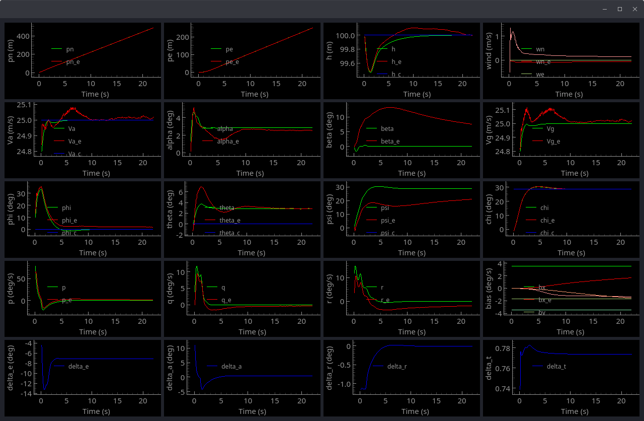
In these plots, the green lines represent ground truth, the red lines represent the estimated state, and the blue values represent the commanded states. Note that not all plots have a commanded state. Additionally, the $\phi$ and $\theta$ plots have a commanded state, but those commands are ignored in the LQR control scheme used in this simulation.
Also note the scaling of the values on each individual plot. Most of the values converge rather quickly to the ground truth. The bias values (4th row and column), however, take a long time to converge to the truth values.
The image below shows the steady-state response of the filter, once the biases have converged to the correct values.
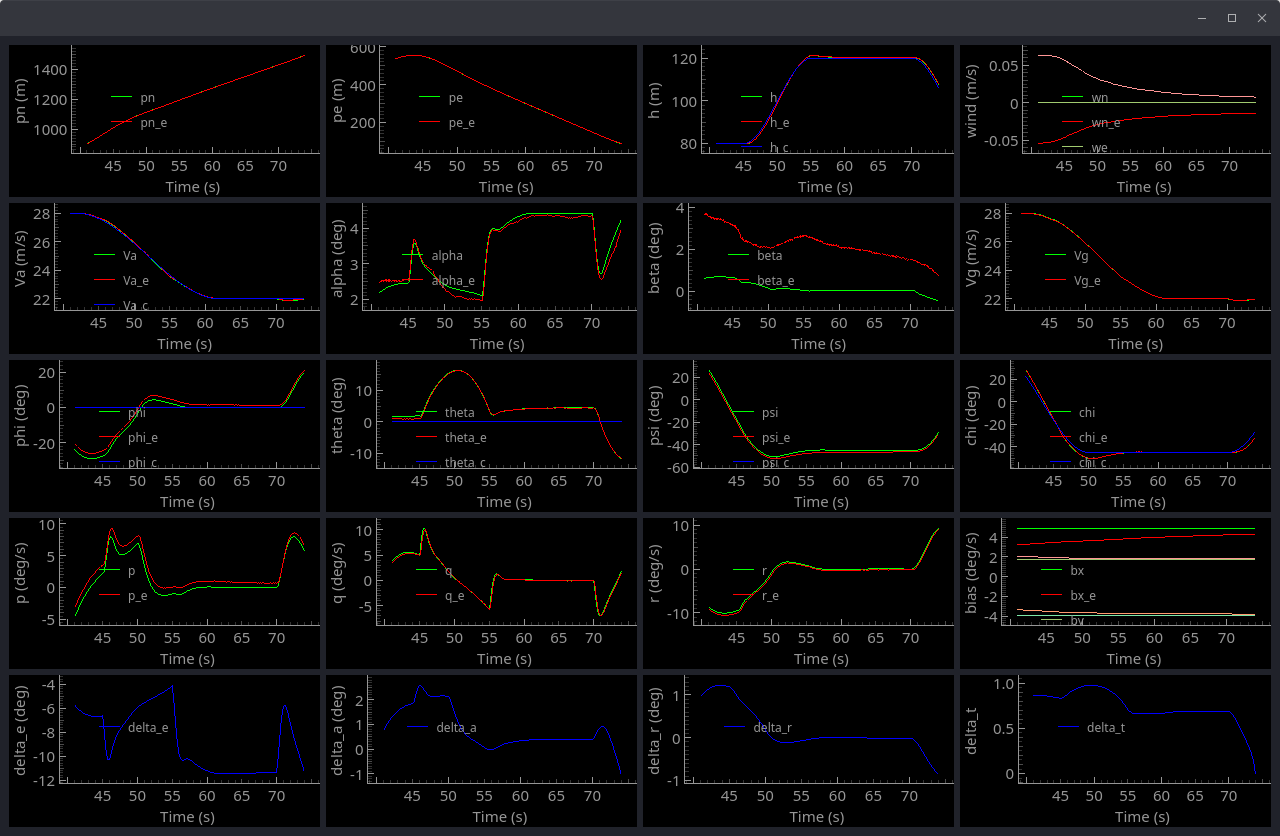
Note that for these plots, the aircraft is maneuvering as shown in the figure below.
For this filter, we used barometer, airspeed sensor, GPS and wind triangle pseudo measurement updates.